The key when producing gear oils is not only to secure the right ingredients, but also effective mixing of the base oils and additives. In collaboration with simulation specialist TeSolva, FUCHS has developed a numeric process that simulates and visualizes all aspects of the dispersion process. This allows production equipment to be adapted quickly to meet increased demand.
The automotive industry is going through a period of transformation. This also affects the lubricants used for initial filling of vehicles, which need to be made available in ever more flexible batches. In growing markets, it is for example important to be able to scale up the production equipment used for gear oils. Yet when seeking to scale up an existing system, the engineers need to ensure that the dispersion process and the distribution of the individual components in the production container can continue to meet the strict requirements in terms of mixing base oils and additives despite the larger dimensioning. “Until now, empirical values and testing with prototypes were often used in cases such as this,” reports Daniel Kieser, Process Engineer at FUCHS SCHMIERSTOFFE. “However, this approach is very time-consuming and not always very efficient.”
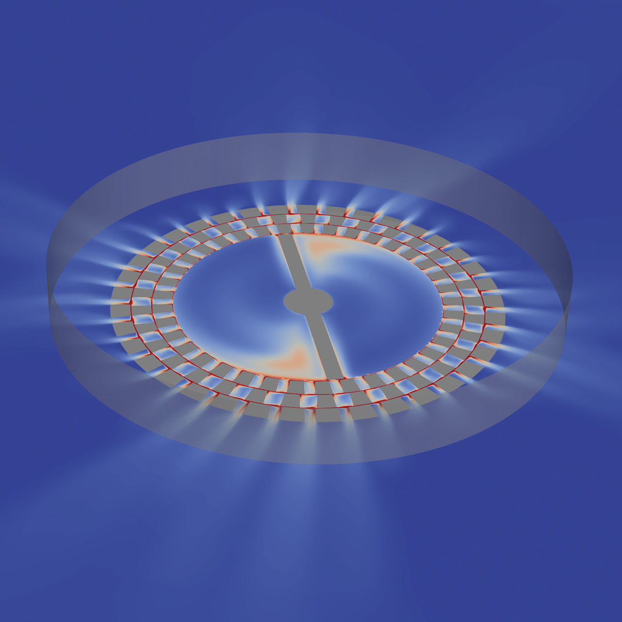
The simulation experts from FUCHS and TeSolva were particularly interested in the procedures directly at the dispersion head.
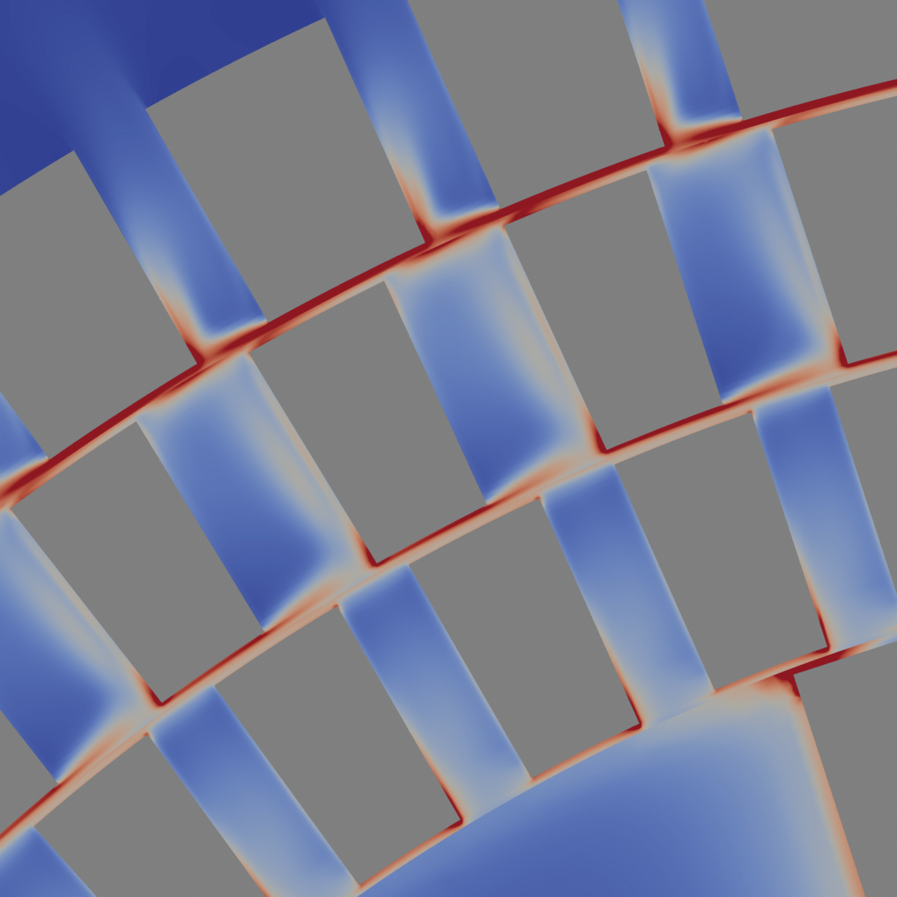
It was possible to visualize the fine distribution of the defoaming agent at the dispersion teeth using computational fluid dynamics (CFD).
SIMULATING THE DISPERSION PROCESS
A promising approach to minimizing costs, while at the same time securing high quality in the upscaled production equipment, focuses on use of virtual processes such as computational fluid dynamics (CFD). In collaboration with simulation specialist TeSolva, FUCHS has developed a numeric process of this kind to simulate and visualize all aspects of the dispersion process used in the production of a gear oil. The objective here is to hone in on solutions to fluid mechanical issues using numeric methods in a three-dimensional model. To this end, the CFD simulation calculates the fluid flows in a system, in particular taking into account the directions and speeds of both gases and liquids under the influence of shearing forces to which they are, for example, subjected by the disperser in the production container.
However, this quickly leads to massive data volumes which push even the latest computer systems to their limits. “A three-dimensional CFD calculation can take days, weeks, or even months,” comments Thomas Kroth, Calculation Engineer at TeSolva. “So it is important to strike the right balance between computing time and the quality of the results.” Finding the right solution at a reasonable cost firstly requires the respective issue to be effectively and precisely defined. “We also worked closely with our colleagues from FUCHS SCHMIERSTOFFE to define precisely which simplifications can be implemented without watering down the results,” reports Kroth.
“We defined precisely which simplifications can be implemented without watering down the results.”
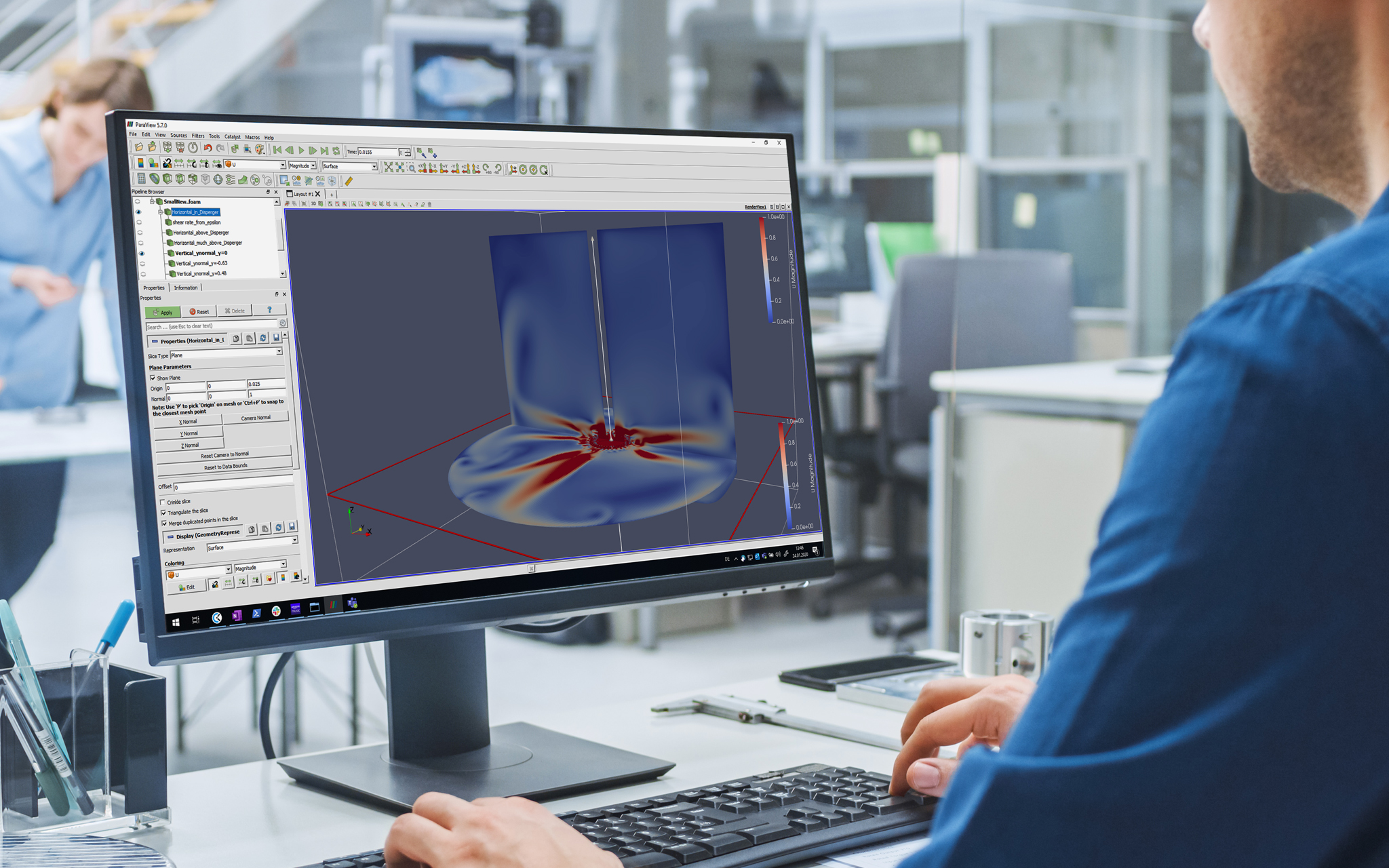
The simulation not only covers the near field, but also the fluid flows in the entire container.
OPTIMUM DISTRIBUTION OF THE DEFOAMING AGENT DROPLETS
In this case, the simulation focused on the pre-disperser, which plays a key part in the so-called „ultra-high-dispersed“ (UHD) gear oil produced using the system. After all, the primary objective with these gear oils is to secure a homogeneous and fine distribution of the defoaming agent droplets during the production process in order to avoid any undesired sedimentation. The shelf life of the lubricant is also increased in this way and an optimum effect of the defoaming agent is achieved during application – the goal of which is to avoid trapped air in the gear oil. UHD gear oils are therefore produced in a two-stage process. First of all, the defoaming agent and further additives are pre-mixed with a small amount of base oil in a pre-dispersion container. In the main process, the pre-processed mixture is then combined with the remaining base oil and further additives in the production container.
“The procedures in the direct vicinity of the disperser are particularly interesting here,” comments Process Engineer Daniel Kieser. “In the simulation, we therefore investigated how precisely the defoaming agent is distributed in the fluid by the teeth on the dispersion head – in other words, whether the energy input is sufficient.” However, it was also important to assess the procedures in other sections of the container. The simulation experts therefore used a lattice grid to divide the whole container into individual zones of various size. The finer the mesh in these zones, the more accurately the flows are calculated, although the lattice is intentionally left coarser in a few relevant sections. “The mix of near field and far field simulation was the actual challenge,” explains TeSolva expert Thomas Kroth.
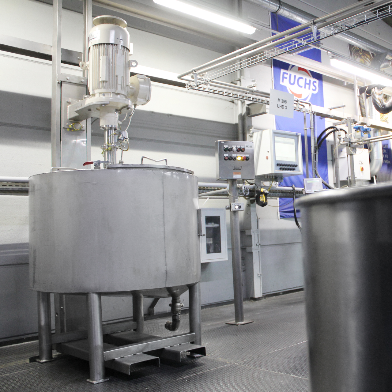
The numerical simulation of the currents and turbulences was initially developed for a smaller container and then scaled to one five times bigger.
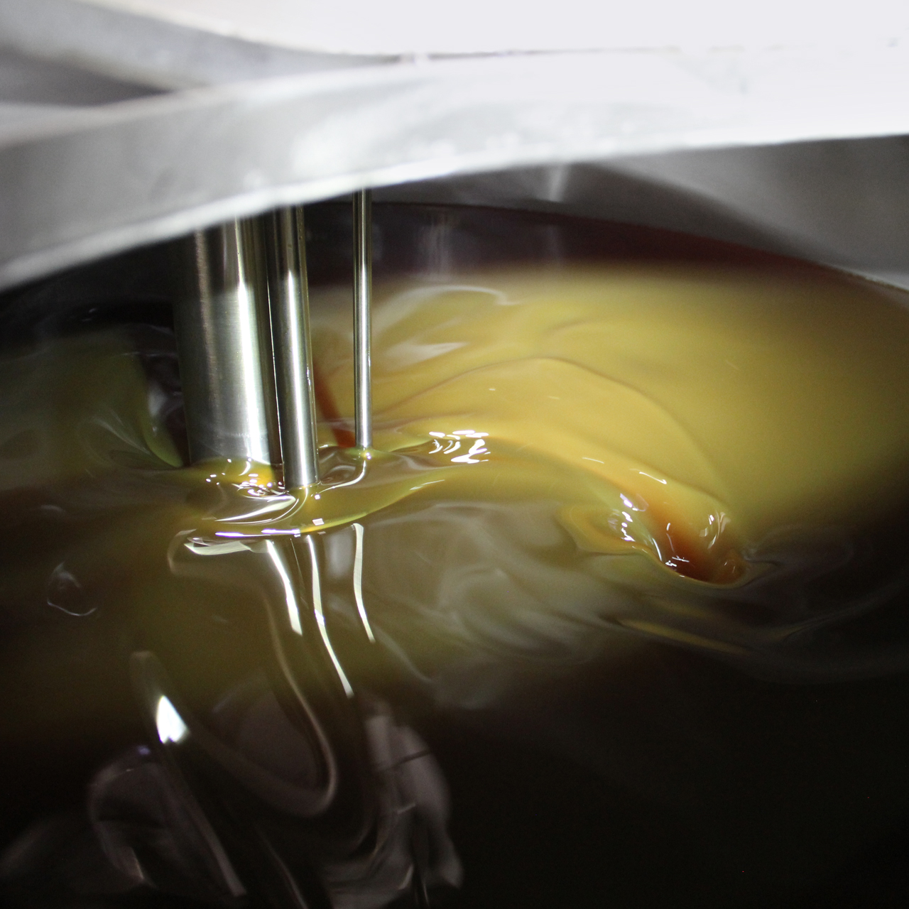
Production plants for gear oils need to be able to scale up quickly. The distribution of the components in the production container always has to meet the stringent mixing requirements when this is done.
“We were able to demonstrate with the simulation that scaling up from the small to the larger system works well.”
SIMULATION SCALED UP TO CONTAINERS OF FIVE TIMES THE SIZE
The numeric simulation of the flows and turbulences in the fluid was first developed for a smaller, already existing container and compared with the real shearing forces and flow rates calculated from the energy input. The simulation was then scaled to a container of five times the size in order to determine whether the shearing forces and flow rates also match up in this case and whether certain parameters – such as the geometry of the container or the position of the disperser – needed to be adjusted. “We were able to demonstrate with the simulation that scaling up from the small to the larger system works well,” reports Kieser. “The project shows that the simulation methods are highly effective and will enable us to align production equipment even more accurately to the requirements of our customers in future.” The large system, verified on the basis of the simulation, is currently under construction and will shortly be used to produce the UHD gear oil for initial filling of vehicles from a leading vehicle manufacturer.
CFD simulation as an animation: comparing the flows and turbulences with the shearing forces and flow rates.


